Join the club
Get exclusive deals and early access to new products.

MikroElektronika
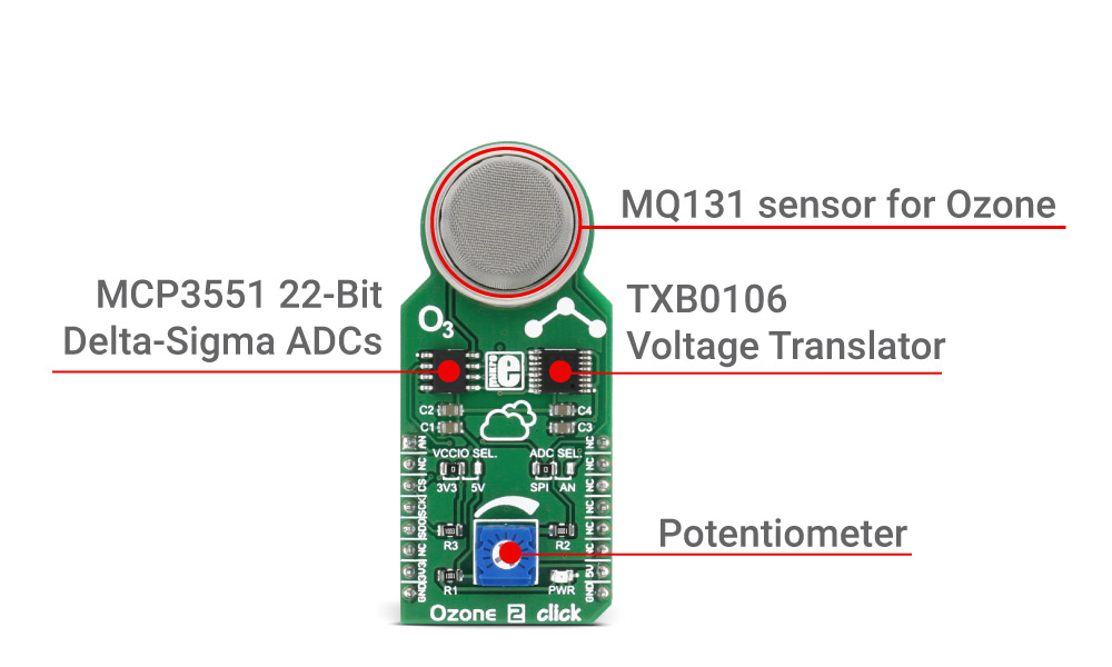
Ozone 2 click carries an MQ131 sensor for Ozone (O3). The sensor outputs an analog voltage, which is converted by the onboard MCP3551 22-bit ADC converter or it is sent to the microcontroller via AN pin on the mikroBUS™, depending on the position of ADC SEL. jumper. The click is designed to run on 5V power supply. It communicates with the target microcontroller over SPI interface or AN pin on the mikroBUS™ line.
Note: The click carries TXB0106 Voltage Translator. For selecting the interface voltage level, use the onboard jumper, and choose between the 3.3V and 5V. For more information, see the Jumpers and Settings table below.
MQ131 is a semiconductor sensor for Ozone (O3). The gas sensing layer on the sensor unit is made of Tin dioxide, which has lower conductivity in clean air. The sensor’s conductivity is higher with the rising of the gas concentration. The sensor consists of micro Al2O3 ceramic tube, Tin dioxide sensitive layer, measuring electrode and heater fixed into stainless steel net. The heater provides necessary conditions for the proper functioning of the sensitive components.

To calibrate the sensor for the environment you’ll be using it in, Ozone 2 click has a small potentiometer that allows you to adjust the Load Resistance of the sensor circuit. For precise calibration, the sensor needs to preheat (once powered up, it takes 48h to reach the right temperature).
| Type | Gas |
| Applications | It can be used in different Ozone concentration detectors for air quality control, or for gas leak detection. |
| On-board modules | MQ131 sensor, MCP3551 |
| Key Features | Ozone concentration 10-1000 ppm, communicates over the AN pin or ADC MCP3551, sensitivity Rs(in air)/Rs(in 50 ppm O3)≥3, onboard potentiometer for calibration |
| Interface | SPI |
| Input Voltage | 3.3V or 5V |
| Compatibility | mikroBUS |
| Click board size | L (57.15 x 25.4 mm) |
This table shows how the pinout on Ozone 2 click corresponds to the pinout on the mikroBUS™ socket (the latter shown in the two middle columns).
| Designator | Name | Default Position | Default Option | Description |
|---|---|---|---|---|
| JP1 | VCCIO SEL. | Left | 3V3 | Power Supply Voltage Selection 3V3/5V, left position 3V3, right position 5V |
| JP2 | ADC SEL. | Left | EXT | Analog signal selection. Left position ADC located on the click board, right position AN pin of mikroBUS™ |
| Designator | Name | Type (LED, BUTTON...) | Description |
|---|---|---|---|
| LD1 | PWR | LED | Power LED, lights green when power supply is established properly. |
Code examples for Ozone 2 click, written for MikroElektronika hardware and compilers are available on Libstock.
The following code snippet outputs data from Ozone 2 click ADC reader via UART
01: void Ozone_2_Task()
02: {
03: uint32_t readValue;
04: uint8_t loggerTxt [40];
05: readValue = OZONE2_Read();
06: LongToStr(readValue, loggerTxt);
07: UART1_write_text("rnRead value:");
08: UART1_write_text(loggerTXT);
09:
10: delay_ms(1000);
11: }