
UT-L 7-SEG R click


MikroElektronika
UT-L 7-SEG R click
Description
UT-L 7-SEG R click carries two SMD ultra thin (3.1mm) LED 7-SEG displays and the MAX6969 constant-current LED driver from Maxim Integrated. The click is designed to run on either 3.3V or 5V power supply. It communicates with the target microcontroller over SPI interface.
Display features
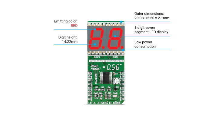
How the click works
The 7 segment displays are interfaced to the MCU over the MAX6969 16-port, constant-current LED driver IC.
It uses the common 4-wire serial bus for communication with MCU itself (LE, SCK, SDO, SDI on mikroBUS™ pin socket).
There is an additional OE (output enable) pin which is used to control the output driver state (enabled/disabled). Since it is the PWM output pin on the mikroBUS™ by default, the LED segments light intensity could be controlled by software too.
MAX6969 driver features
The MAX6969 uses the industry-standard, shift-register-plus-latch-type serial interface.
The driver accepts data shifted into a 16-bit shift register using data input DIN and clock input CLK. Input data appears at the DOUT output 16 clock cycles later to allow cascading of multiple MAX6969s. So, the IC allows you to connect multiple click boards™ - for applications that require more than two seven segment displays, such as digital clocks, temperature sensors, etc.
Specifications
| Type | LED Segment |
| Applications | Displaying digits and letters on two 7 segment displays |
| Displays | DSM Series Ultra Thin Surface Mount Single Digit 7-Segment LED Display |
| On-board modules | MAX6969 6-Port, 5.5V Constant-Current LED Driver |
| Key Features | Excellent character appearance, low power consumption |
| Interface | GPIO,SPI |
| Input Voltage | 3.3V or 5V |
| Click board size | L (57.15 x 25.4 mm) |
Pinout diagram
This table shows how the pinout on UT-L 7-SEG R click corresponds to the pinout on the mikroBUS™ socket (the latter shown in the two middle columns).
| Notes | Pin | Pin | Notes | ||||
|---|---|---|---|---|---|---|---|
| NC | 1 | AN | PWM | 16 | OE | PWM control of light intensity | |
| NC | 2 | RST | INT | 15 | NC | ||
| Load-Enable input | LE | 3 | CS | TX | 14 | NC | |
| Clock input | SCK | 4 | SCK | RX | 13 | NC | |
| Serial Data Output | SDO | 5 | MISO | SCL | 12 | NC | |
| Serial Data Input | SDI | 6 | MOSI | SDA | 11 | NC | |
| Power supply | +3.3V | 7 | 3.3V | 5V | 10 | +5V | Power supply |
| Ground | GND | 8 | GND | GND | 9 | GND | Ground |
Jumpers and settings
| Designator | Name | Default Position | Default Option | Description |
|---|---|---|---|---|
| JP1 | PRW.SEL. | Down | 3V3 | Power Supply Voltage Selection 3V3/5V, down position 3V3, up position 5V |
Programming
Code examples for UT-L 7-SEG R click, written for MikroElektronika hardware and compilers are available on Libstock.
Code snippet
The following code snippet counts down from 99 to 0 on the displays of the UT-L 7-SEG R click.
01 sbit MAX6969_LE_PIN at RC2_bit;
02 sbit MAX6969_LE_PIN_Direction at TRISC2_bit;
03
04 uint16_t pwmPeriod;
05 static const uint8_t minus_char = 0x40;
06
07 void systemInit()
08 {
09 AD1PCFG = 0xFFFF;
10 MAX6969_LE_PIN_Direction = 0;
11 SPI3_Init();
12 pwmPeriod = PWM_Init(5000, 1, 1, 2);
13 PWM_Start(1);
14 PWM_Set_Duty(pwmPeriod/10, 1);
15
16 }
17
18 void MAX6969_Chip_Select()
19 {
20 MAX6969_LE_PIN = 1;
21 asm nop
22 asm nop
23 asm nop
24 MAX6969_LE_PIN = 0;
25 }
26
27 static void U7SEG_Write(uint8_t number)
28 {
29 char numbers[10] = {0x3F, 0x06, 0x5B, 0x4F, 0x66, 0x6D, 0x7D, 0x07, 0x7F, 0x6F};
30 uint8_t tens = number / 10;
31 uint8_t ones = number % 10;
32 if (number > 99) return;
33
34 SPI_Wr_Ptr(numbers[ones]);
35 SPI_Wr_Ptr(numbers[tens]);
36 }
37
38 void main()
39 {
40 uint8_t counter;
41
42 systemInit();
43 counter = 100;
44
45 while(counter--)
46 {
47 U7SEG_Write(counter);
48 MAX6969_Chip_Select();
49 Delay_ms(500);
50 }
51
52 SPI_Wr_Ptr(minus_char);
53 SPI_Wr_Ptr(minus_char);
54 MAX6969_Chip_Select();
55 }