
DC MOTOR 4 click


MikroElektronika
DC MOTOR 4 click
Description
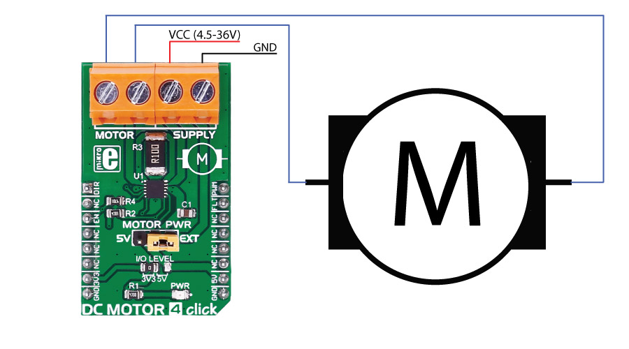
DC MOTOR 4 click is capable of driving motors with a supply voltage from 4.5V to 36V. It carries the MAX14870 motor driver from Maxim Integrated. The click is designed to run on either 3.3V or 5V power supply. DC MOTOR 4 click communicates with the target MCU over the following pins on the mikroBUS™ line: PWM, AN, CS, and INT.
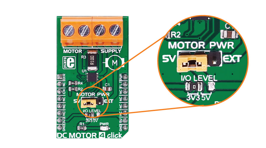
The J2 jumper onboard the click is used for selecting a power supply - either the onboard 5V or the external DC motor power supply input.
DC MOTOR 4 click can be used to driving DC motors, controlling the motor's speed, the direction of the rotation, as well to brake and regulate the current.
MAX14870 driver features
The MAX14870 motor driver offers a small, low power solution for driving and controlling brushed DC motors and relays with voltages between 4.5V and 36V.
Very low driver on-resistance reduces power dissipation. It features a charge-pump-less design for reduced external components and low supply current.
How the click works
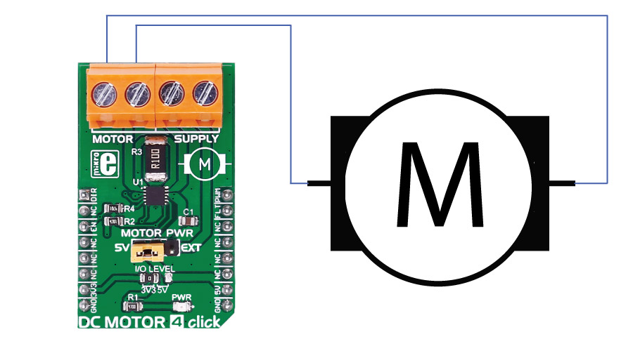
There are two onboard screw terminals - one is for connecting the DC motor, and the other one is for connecting an external source if necessary. The DC motor is controlled through PWM, CS and AN pin of the click board.
Specifications
| Type | DC |
| On-board modules | MAX14870 motor driver |
| Key Features | The click is capable of driving motors between 4.5V and 36V |
| Interface | GPIO,PWM |
| Input Voltage | 3.3V or 5V |
| Click board size | M (42.9 x 25.4 mm) |
Pinout diagram
This table shows how the pinout on DC MOTOR 4 click corresponds to the pinout on the mikroBUS™ socket (the latter shown in the two middle columns).
| Notes | Pin | Pin | Notes | ||||
|---|---|---|---|---|---|---|---|
| Rotation direction | DIR | 1 | AN | PWM | 16 | PWM |
PWM Control Logic Input |
| NC | 2 | RST | INT | 15 | FLT |
Open-Drain Active-Low Fault Output |
|
| Enable IC | EN | 3 | CS | TX | 14 | NC | |
| NC | 4 | SCK | RX | 13 | NC | ||
| NC | 5 | MISO | SCL | 12 | NC | ||
| NC | 6 | MOSI | SDA | 11 | NC | ||
| Power supply | +3.3V | 7 | 3.3V | 5V | 10 | +5V | Power supply |
| Ground | GND | 8 | GND | GND | 9 | GND | Ground |
Buttons and LEDs
| Designator | Name | Type | Description |
|---|---|---|---|
| PWR | PWR | LED | Power LED, lights green when Board is powered. |
Jumpers and settings
| Designator | Name | Default Position | Default Option | Description |
|---|---|---|---|---|
| JP1 | Data level | Left | 3V3 | Data Level Voltage Selection 3V3/5V, left position 3V3, right position 5V |
| JP2 | Supply selection | Power supply selection EXT/5V, right position EXT, left position 5V |
Programming
Code examples for DC MOTOR 4 click, written for MikroElektronika hardware and compilers are available on Libstock.
Code snippet
The following code snippet shows the initialization and use of compiler built-in PWM functions to control the motor.
01 void systemInit()
02 {
03 GPIO_Digital_Output(&GPIOA_BASE, _GPIO_PINMASK_4);
04
05 pwmPeriod = PWM_TIM5_Init(1000); // Set PWM frequency/period (according to the DC motor characteristics)
06 PWM_TIM5_Set_Duty(pwmPeriod, _PWM_NON_INVERTED, _PWM_CHANNEL1); // Set current duty for PWM
07 PWM_TIM5_Start(_PWM_CHANNEL1, &_GPIO_MODULE_TIM5_CH1_PA0); // Start PWM
08
09 }
10
11 void main()
12 {
13
14 systemInit();
15
16 while (1)
17 {
18 //Forward
19 DIR_PIN = 0;
20 //Forward fast
21 PWM_TIM5_Set_Duty(pwmPeriod, _PWM_NON_INVERTED, _PWM_CHANNEL1);
22 Delay_ms (3000);
23 //Forward slow
24 PWM_TIM5_Set_Duty(pwmPeriod/2, _PWM_NON_INVERTED, _PWM_CHANNEL1);
25 Delay_ms (3000);
26 //Reverse
27 DIR_PIN = 1;
28 //Reverse fast
29 PWM_TIM5_Set_Duty(pwmPeriod, _PWM_NON_INVERTED, _PWM_CHANNEL1);
30 Delay_ms (3000);
31 //Reverse slow
32 PWM_TIM5_Set_Duty(pwmPeriod/2, _PWM_NON_INVERTED, _PWM_CHANNEL1);
33 Delay_ms (3000);
34
35 }
36 }